Article on The Internet Mini Encyclopædia |
Header
SSI Insert revised (no index tag!): 22-Feb-2016
Article on The Internet Mini Encyclopædia |
Text and photos from Stuart King in New Zealand (added 14 January 2006):
The following circuit was created as a way of making the meter part of the Smiths RVI tachometer I bought off of EBay work with the Electronic ignition fitted to my Mini. It is largely based on the "Current Driven Meter" circuit found in the 'National Semiconductors LM2917 integrated circuit (IC)' Datasheet (on page 10) and my thanks go them for making this very useful circuit available!
Let me preface this by saying my knowledge of electricity and electronics is pretty cagey - having learnt most of it over the last 4-5 months! This circuit works on the bench - and on the garage floor - I've not yet boxed on up inside the meter so can't say for sure how well or long this will work for - it appears to be okay to me though!
I'm not going to tell you how to solder or assemble this, just what I did, and what you need to repeat my work - you may need some trial and error, I recommend a breadboard - and a multimeter is a definitely must - check the voltages and current everywhere before you hook things like the IC and your meter up!
You WILL need to disassemble your Rev-Counter/Tachometer - this can be hard on the crimp sealed tachometers, I recommend a Dremel style tool with a small cutting disc - run this around the edge, leaving 3-4 tabs evenly spaced. Bend these tabs up slowly and pull the face off - be careful finding replacement glass and other bits will be a pain!
Make sure you measure the resistance across your meter (see the disassembling bit below)! Mine have been 13 to 60 ohms - higher is preferable, but this circuit has been designed to cope with as low as 10 ohms! You can test your meter by running 50mA (a seemingly reasonable and common current) through it by connecting it to a 30ohm resistor and then to a 1.5v battery.
A good start for this project is to read the LM2917 Datasheet as this will help give you an idea of what mysterious things the IC is doing when you apply a signal (usually from the -ve side of the tachometer) to pin 1.
How it works:
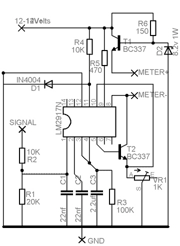
The circuit (shown below) is connected between the +ve switched feed from the vehicles ignition (usually 12v when the engine is off and 12.7-14v when on), and the chassis (GND). The signal is taken from the -ve side of the ignition, and it run through a resistor voltage divider (R1 and R2), this reduces the voltage fed into the IC to 2/3's of what it would be, and severely limits the current which stops the coil being constantly grounded and failing to fire. The capacitors (C1 and C2) do have a function but I'll ignore it here, read the Datasheet if you want to know).
 Some
magic happens and the pulses on the signal feed are detected by the IC and converted
to a steady voltage (dictated by R3) - this is kept stable by the feedback loop
running around/through the Operational Amplifier (OpAmp) inside the IC - in
this case I've added an extra transistor to the loop allowing a higher current
drain (800mA max as opposed to the 50mA max allowed by the IC). Usually the
transistor (an NPN) would mean you'd gain .7v (the amount required to switch
it on - sometimes called a voltage drop), but because it's kept in the feedback
loop the OpAmp adjusts and keeps it at the right level. The IC works by raising
the voltage as the frequency of the signal increases (the rpm of the engine),
the side effect of which is an increase in current which will drive the meter.
In the configuration I've set up here the IC will allow around 10mA per 1000rpm
(AFAIK this is 33.3hz per 1000rpm for a 4 cylinder 4 stroke engine) this can
be calibrated (a different story altogether!) using the Trim-Pot VR1.
Some
magic happens and the pulses on the signal feed are detected by the IC and converted
to a steady voltage (dictated by R3) - this is kept stable by the feedback loop
running around/through the Operational Amplifier (OpAmp) inside the IC - in
this case I've added an extra transistor to the loop allowing a higher current
drain (800mA max as opposed to the 50mA max allowed by the IC). Usually the
transistor (an NPN) would mean you'd gain .7v (the amount required to switch
it on - sometimes called a voltage drop), but because it's kept in the feedback
loop the OpAmp adjusts and keeps it at the right level. The IC works by raising
the voltage as the frequency of the signal increases (the rpm of the engine),
the side effect of which is an increase in current which will drive the meter.
In the configuration I've set up here the IC will allow around 10mA per 1000rpm
(AFAIK this is 33.3hz per 1000rpm for a 4 cylinder 4 stroke engine) this can
be calibrated (a different story altogether!) using the Trim-Pot VR1.
In order to stop the IC and Transistor strapped to it overheating (due having
to dissipate to the 12-14volts +ve fed into it - around 700mW at 5000rpm which
is over the max of most BC337's!) we have to reduce the voltage - using a Zener
Diode looked like the easiest way to do this. I chose an 8.2v Zener as that
seemed to work (giving around 410mW at 50mA) though going to 7.5v or even 5v
could work well too. The current that the Zener Diode and the base of the transistor
are fed is limited by R6, the Zener passing 8.2v onto the base of the other
transistor, the net result being that the transistor allows 8.9v (that's 8.2v
+ .7v for the voltage-drop effect as I mentioned above) which means we have
to dissipate 445mW, a little more than the 8.2v would give but much less than
with 14v!
The meter is connected between the + and - markings, usually there is a small red lead from the old PCB inside the meter which will usually the +ve side. The black being the -ve. I would recommend unsoldering these from the PCB to stop any WEIRD behaviour.
Calibration:
It is important to understand that your meter will NOT be perfect - nothing is! The circuitry and meter will be affected by voltage fed into it, temperature and possibly all manner of other things! I would hope for around + or - 100rpm accuracy though it may be better. You could try adding a linear voltage regulator (say a 1A type max like a LM7809, a 100mA max 78Lxxxx won't cut it!) to improve things - but I'm not sure it will help all that much. If you leave your meter running on a calibration circuit, you'll see it change over 5mins or so - I let mine warm up like this before calibrating it as it seems to return to that calibrated value after a short while of driving.
Touching the PCB/components when calibrating can cause the reading to vary by as much as 1000rpm - put your PCB on something nonconductive when calibrating!
The easiest way to calibrate (IMHO) is to build a small circuit based on the 555 timer chip - there are heaps of circuits on the web for these. What you're looking for is an Astable configuration and you'll want to test it at a range of frequencies, I recommend 33.3hz/1000rpm, 66.6hz/2000rpm, 133.33/4000rpm and possibly 200hz/6000rpm if regularly visit those types of speeds! Feed the output of this to the signal feed on the tachometer circuit.
 Alternatively
if you've a good quality rev-counter to test yours against you can hook them
both up and calibrate this way.
Alternatively
if you've a good quality rev-counter to test yours against you can hook them
both up and calibrate this way.
Things you'll need if you want to build this:
Semiconductors:
1 x LM2917N (make sure it's the 14 legged 'N' version,
the 8 leg version won't do, and the non 'N' might get fried from the very irregular
voltages found in cars)
2 x BC337 Transistors (these were chosen for their 800mA rating and low cost,
though something as low as 500mA would probably do)
1 x IN4004 Diode (or similar - as per the Datasheet)
1 x 1N4738 Zener Diode (8.2v 1W, though 5-7V would probably work)
Resistors (I used 1% accuracy ones, probably the best idea, K = 1000, so 100K = 100,000):
1 x 100K resistor (for 4 cylinder cars, see the datasheet
for other numbers of cylinders)
1 x 20K 1/2W Resistor
2 x 10K 1/2W Resistor
1 x 470 1/2W Resistor
1 x 150 1/2W Resistor (200 or even 300 would be fine too)
1 x 1K 1/2W Trim-Pot (I used a Bourns 25 turns Pot – it is possibly that
a 100ohm Pot would have worked just as well)
Capacitors (I used 100V MKT caps, because of the possibility of high transient voltages from the ignition coil):
2 x 22nF Capacitors
1 x 2.2uF Capacitor (this suppresses small changes in RPM, but can also slow
the rate at which the meter changes - 2.2uF seems about right for my Smiths
meters)
Other stuff:
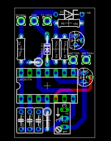
PCB - Either a pre-made PCB (from the design to the left) or a small Prototyping board (pictured).
Wire - the smallest size that fits through the holes in the PCB - I'm not sure how this is measured but PCB holes are usually .9mm to 1mm.